
As I mentioned before in the tutorial introduction, paper model template design is a series of steps using 3 co-operative softwares. We’re going to use drawing software [inkscape], 3d modeling software [gmax] and 3d unfolding software [pepakura 3d designer]. Because the long list of have to do on each steps I’ll focus on 3d modeling with paper modeling approach and a glance on how to export our 3d model into 3d unfolding software in this tutorial. I'm not going to wait until all the tutorial of this step is complete, I'll upload whenever is ready and will continue until it finish, so make sure to check this page everyday
Collecting Data :
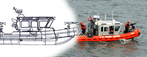
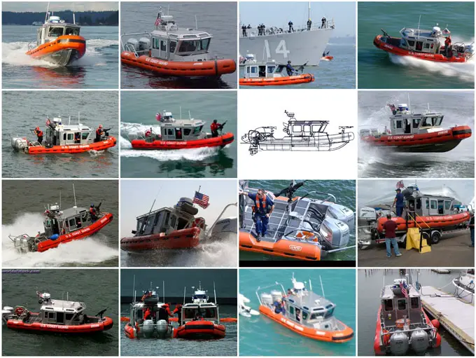
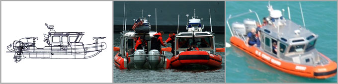
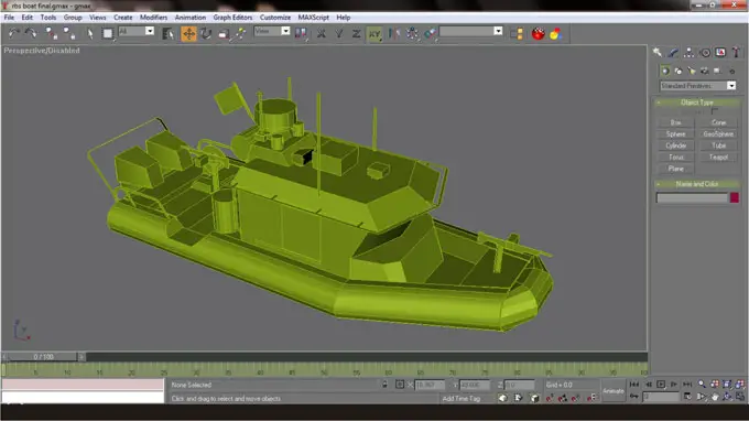
I have Google and collect some images of our subject, a US Coast Guard Response Boat Small [RBS]. Each image has different angle and different details seen in all of them, each image is very useful to build a whole image and 3d geometry image of our subject in our brain. We now see how it will looks like, but we have to simplify that image into 2 or 3 view drawing or blueprint. Blueprint will make 3d modeling much easier, it will be our guide.
Making blueprint :
Luckily we have one side view drawing and with 2 other important images I managed to draw a simple blueprint we need with inkscape by using “freehand lines” tool [F6]. First I import a side view drawing into inkscape by dragging the image off from explorer and drop it onto inkscape workspace and choose embed for that image properties. Then I resized it by dragging the diagonal pointer and press Ctrl in the same time, it made the image resized uniformly. Then I change image opacity into 30 and then start trace it using Freehand lines tool [F6]
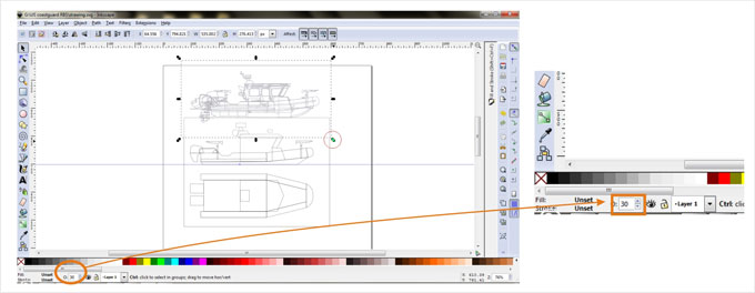
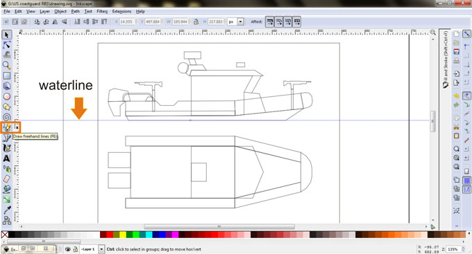
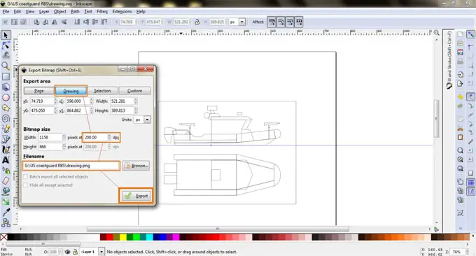
I have decided to model a “waterline” type of model boat, that’s mean we’re going to model boat parts that we actually seen above the water, we won’t make parts that submerge under water. The next step is to export the drawing into bitmap [PNG]. Draw a box surround our drawing with “create rectangles and squares” tool [F4]. Click File - Export Bitmap, when dialog window open, choose Drawing and fill dpi with 200 dpi on Bitmap size. Save as drawing.png and drawing.svg.
Preparing Blueprint on Gmax :
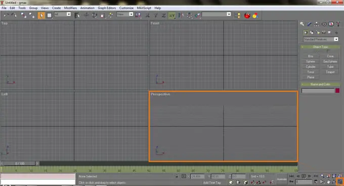
Open Gmax, it comes with 4 viewports and choose Perspective then click “min/max” toggle in the bottom right corner icon.
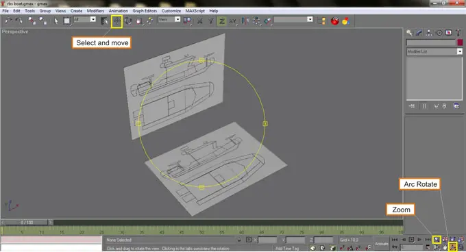
On perspective viewport try to familiarize rotating and panning the viewport. Click “Arc rotate icon” then place your mouse cursor inside a yellow circle inside perspective viewport then click and hold the left mouse button and drag left and right, up and down. Always drag inside the yellow circle because if you drag outside the circle you will ruin the horizon orientation on the viewport and you will get confused :p. Remember this is how to rotate the viewport or change your point of view not the object in it.
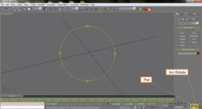
Click on the Pan icon, then drag with holding left mouse button left or right and up or down to pan the viewport. You can also panning while in Arc rotate mode by holding middle mouse button and drag your mouse.
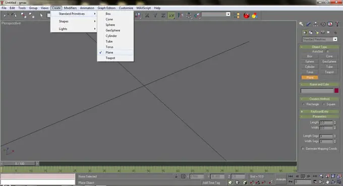
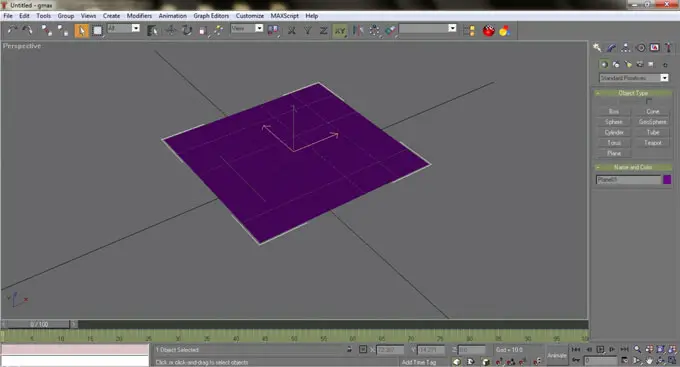
Now we’re going to create a plane geometry to be the blueprint container. There are two ways to create a plane. First by using upper menu : Click Create menu - choose Standard Primitives - then click Plane. Drag mouse to create a plane. Secondly by using right toolbar rollout, click on the cursor icon [Create], The default rollout will be Standard Primitives and choose Plane. Drag mouse on the viewport to create a plane.
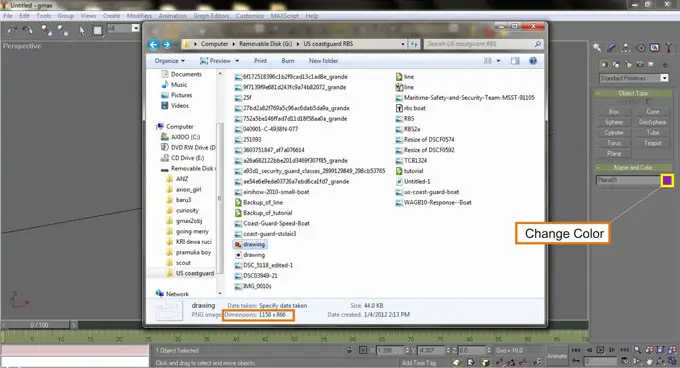
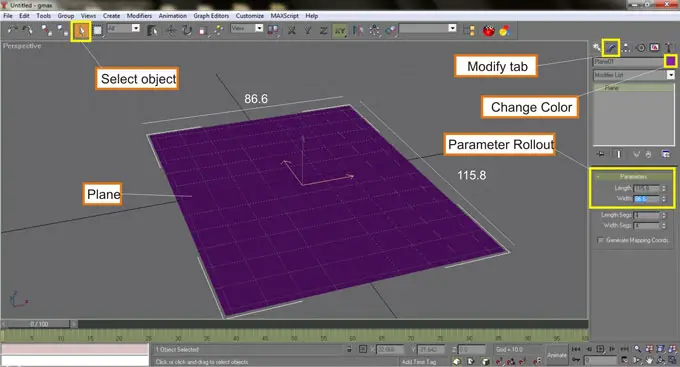
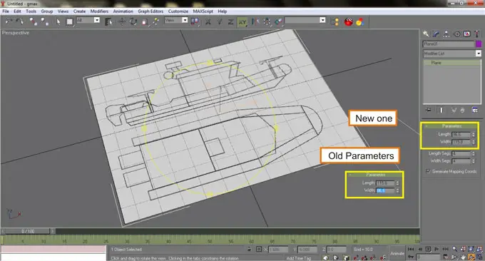
We have to adjust the plane dimension to match blueprint image width and length ratio. The drawing.png is 1158 x 866 pixel. Select the plane by choosing select the cursor button on the top toolbar first then click or select the plane. Go to right toolbar rollout then select “modify” tab and edit the width and the length with 115.8 and 86.6 so the plane will match the blueprint image ratio. The color of the plane that you create may not with same color as I make, because gmax always randomize the created object color. You can change the color by clicking on a color box on the Name and Color rollout or on Modify tab rollout, then change it into purple.
Drag the blueprint image [drawing.png] and drop it onto the plane, the plane will be instantly change color with blueprint image on the plane. Most of the time, at first the image will be not in the correct orientation, to correct it you have to switch the width with the length.
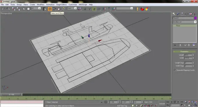
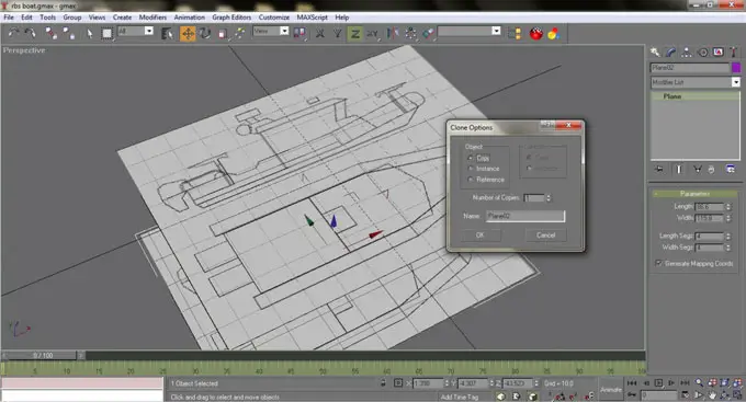
Now we have to copy the blueprint and place them according to the drawing orientation. First blueprint needs to lie horizontally and the second one vertically. Select “select and move” button on the top toolbar, then select the plane if it haven’t selected yet. Hover your mouse on top the “gizmo” [3 arrows colored green, red and blue], hover the mouse over the blue arrow until the line turns yellow then by press and holding the “shift” key first, drag it down then release. It will brings a small dialog window then leave it in default setup which is “Copy” then click ok. Now we have two plane.
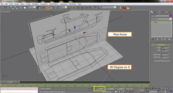
Select the top blueprint then click Select and Rotate button on the top toolbar. Select the red arrow of the gizmo then rotate the plane into 90 degree. Save your work here with the name : rbs boat.gmax
Arrange both blueprints in the way shown on the image below by using “Select and move” tool. Adjust your point of view by using “Arc Rotate” and “Zoom” function. You can zoom and un-zoom by scrolling your mouse wheel up and down. Press “G” key to toggle the 3d grid on or off. Now our blueprint are ready to use.
Click Next to continue to Modeling 3D boat :
Modeling 3D boat :
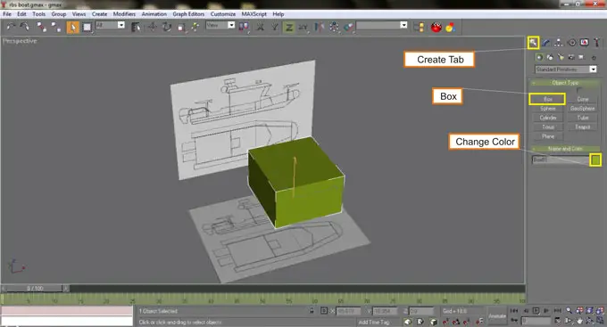
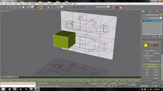
Choose create tab on the right toolbar rollout - standard primitives - and choose Box. Create a box in the middle of the viewport by dragging your mouse and release your left mouse button then move your mouse up to set the box height. Always choose “Select” on the top toolbar after creating an object. Change your box color with green if it’s not in green yet, actually it doesn’t matter what the color is, it’s just to make the box the same as the image on this tutorial, otherwise you may get confused. Don’t forget to save your work again.
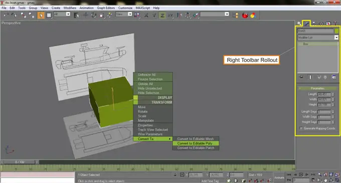
Select your box, right click over it - choose Convert to - then choose Convert to Editable Poly. This step is making the box fully editable. Notice the right toolbar rollout is change, now we have “Selection” rollout on the modify tab.

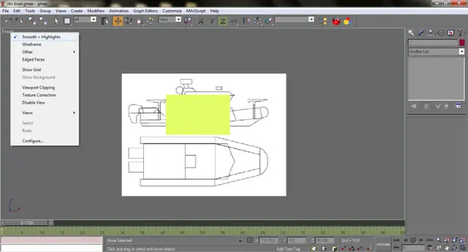
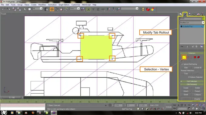
Change your viewport from Perspective into Front view by press F key or by right clicking The perspective Title on the upper left corner of the viewport, then choose Views and choose Front. If your front view is nothing like image below, right click on the viewport title again, then choose Smooth + Highlight, the default setting is Wireframe.
Click F4 to toggle polygonal lines visibility on or off, turn it on. Select the green box and in the modify rollout in Selection rollout choose vertex [3 red dots]. Select each corner and move it to the position shown on the image below as we’re going to build the cabin of the boat. You have to select every corners by dragging your mouse around the blue dot because you need to select actually two vertex, although what you see is only one vertex because both vertex are overlapping.
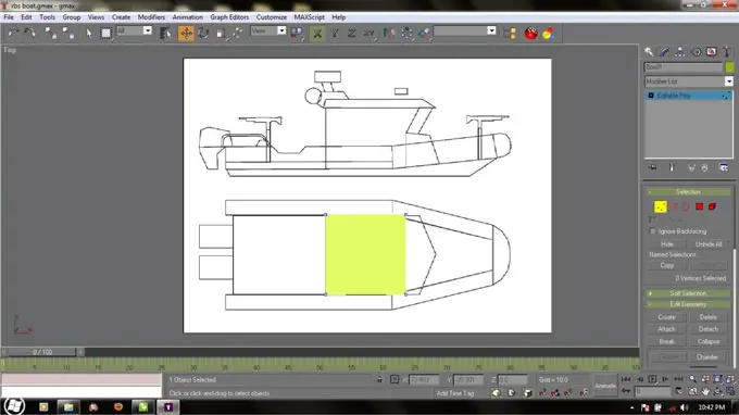
Now change the viewport to the top view, press T key. Do same as the previous work, edit the vertex to match the image below. Now change view into perspective, press P key, Arc Rotate to see what you have done.
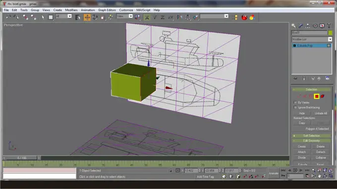
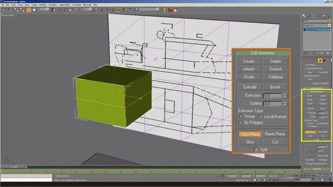
Select Polygon on Modify tab - Selection Rollout. Then select a surface on the box like shown on image below. Scroll down the modify rollout until you find Edit Geometry Rollout, find Slice Plane and click it then click Slice button just below it. Turn off Slice Plane function by click it again, Now you have a split surface on the box.
Select vertex edit mode again and adjust the vertex to match the blueprint, you can switch viewport from Front view by pressing F Key and P key for Perspective view.
Click Next in this page to continue
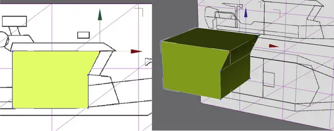
Also using the Slice Plane function I split again both surfaces but this time I rotate the slice plane 90 degree. Now we have 4 segments. Change selection to vertex again move all 3 vertex in the middle and pull out to match the blueprint on the side view [Front View = Press F]
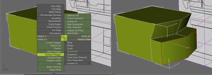
Also using the Slice Plane function I split again both surfaces but this time I rotate the slice plane 90 degree. Now we have 4 segments. Change selection to vertex again move all 3 vertex in the middle and pull out to match the blueprint on the side view [Front View = Press F]. Now we’re going to extrude the 2 bottom surfaces outward. Select polygon selection again then, select both bottom surfaces then right click and choose on TOOLS 2 - Extrude Polygon then pull out the surfaces.

Also using the Slice Plane function I split again both surfaces but this time I rotate the slice plane 90 degree. Now we have 4 segments. Change selection to vertex again move all 3 vertex in the middle and pull out to match the blueprint on the side view [Front View = Press F]. Now we’re going to extrude the 2 bottom surfaces outward. Select polygon selection again then, select both bottom surfaces then right click and choose on TOOLS 2 - Extrude Polygon then pull out the surfaces.
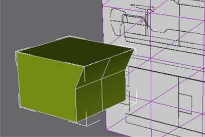
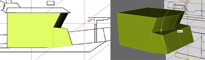
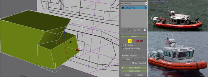
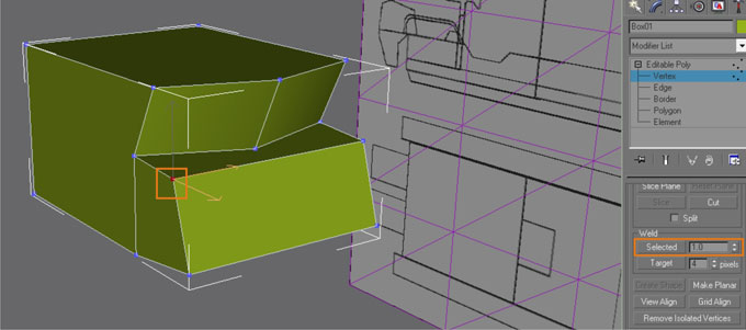
Adjust the geometry using edit vertex [ vertex selection] on front view. Change to Perspective view again to see the result. Now we look at our photo references, we don’t need the line in the middle on the extruded surfaces, we have to remove it. Change selection to Edge then select both lines or edges using Ctrl for selecting multiple objects. Then on edit geometry rollout on Modify tab, find Delete button then click it. Deleted edges always left unused vertex, we have to move the unused vertex overlap to the nearest vertex and weld them. Select both vertex and on the modify tab - edit geometry rollout - scroll down until you find Weld, then click selected, then we will have welded vertex.
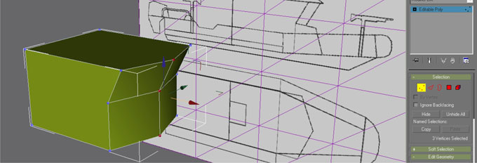
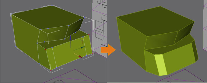
To match the real boat, I split again the front surface into 3 parts then push the outer vertex like shown on image below
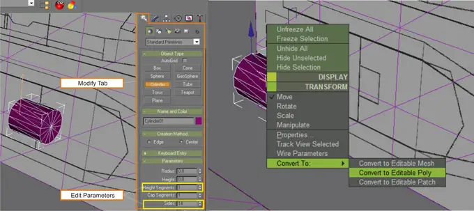
Create a cylinder : Create tab - Cylinder - edit Parameters with 1 height segment and 14 sides. Color your cylinder with purple and convert it into editable poly.
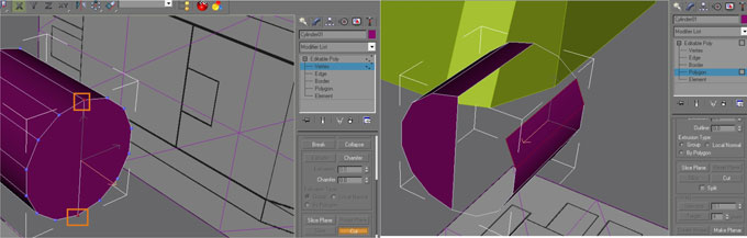
Select the top and bottom vertex shown below and connect both vertex by using Cut function as also shown below, right mouse click to stop the operation. Do same with the back of that cylinder. Then select edit polygon and select and delete the right side of the cylinder.
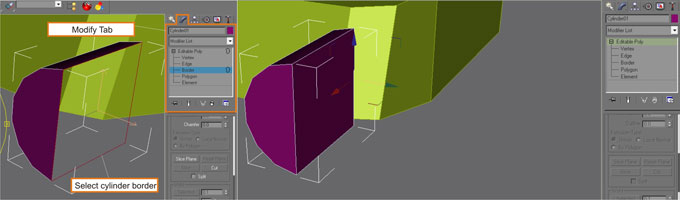
Change edit selection to border, click on the gap hole on the cylinder then right click and find Cap on TOOLS 2 , now we have a closed half cylinder. Click on the border again to end the selection and back to normal again.
Lastest gmax tutorial file download below
TO BE CONTINUED...
Click Next in this page to continue to Exporting 3D model to Pepakura
Exporting 3D model into OBJ file
Ok, looks like we have been dragging on how to modeling 3d object for quite sometime. I will continue the rest of the modeling tutorial eventually, but it might be better if I skip it to how to export our 3d work into pepakura 3d designer known format for a while. I already complete that 3d boat, all is made in Gmax. Actually it is very easy to export a 3d work to pepakura known format, if you have 3D Studio Max, all you have to do is just exporting it to 3DS. But we are using Gmax, and that is a free version dedicated to edit a 3d game model, its format doesn’t have any compatible software. We’re going to use a Max Script to convert our 3d boat into OBJ file, which is one of pepakura known format.
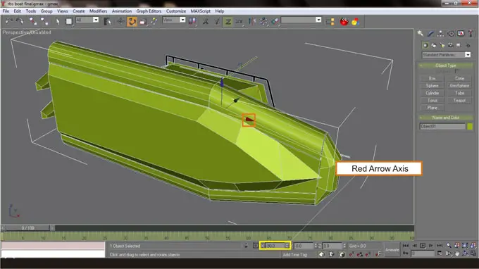
In Gmax rotate the boat -90 degree on the red arrow axis (X Axis) like shown in the image below. We have to do this because there is a different XYZ orientation in OBJ file and while in pepakura. By doing this we will have normal 3d XYZ orientation imported in Pepakura. Many papercraft creators that are using Pepakura, add material first before unfolding the 3d model, but Paper Replika will add the color or material later after all parts are unfolded. Material will be drawn in Inkscape so we will have vector image in PDF like all models in Paper Replika.
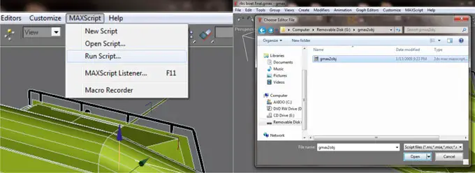
Make sure you already have the Max Script file that I share in the Introduction. The script is gmax2obj, In Gmax : in top menu - MAXScript - Run Script...
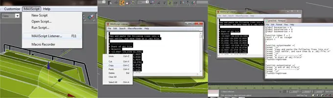
Wait for a while the computer run the script then in top menu click again MAXScript - MAXScript Listener or F11. MAXListener window will open with a list of number, they are coordinates of dots that build up your 3d boat. Copy all the list and paste the list or script on a notepad and save it as boat.obj. In complex objects like our boat here MAXListener only allowed to copy a certain numbers of rows that can be copied, so you have to copy and paste them partially until all are copied to notepad.
Click Next in this page to continue to Setting up the scale
Setting Up The Scale
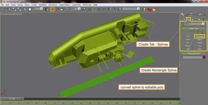
Now we have obj file we need, you can try to open it on Pepakura designer. We are making a paper model here, a not too simple model but not a very detail neither, so we have to state the scale. Many beginners confuse on how to set the scale in their 3d model, in my way the scale will not setup in 3d software but in pepakura. This is how In Gmax again, make a rectangle with Create Splines then convert it into Editable Polygon and adjust it so it has the same length of the overall boat.
Delete the boat and save it as scale.gmax. Export that plane / rectangle to OBJ again. This one is important, always delete all the old script in MAXScript Listener before you run the script again (Edit - Clear All). Run the script again (gmax2obj) then do same as the boat by copy paste the list on a notepad and save it as scale.obj.
Open scale.obj on Pepakura. Choose No Flip then click Finish. Click Unfold button. On the top menu (Pepakura) click 2DPattenWindow - Change the Scale of Development - Specify the scale then new small window, a Change Pattern Size window is open.
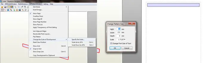
Now we do the math for the scale. The real boat is 9 meter in length, we are going to make a small boat paper model, I like small paper model because all the details will look more sophisticate. Let’s try 1 : 72 scale, we want measurement in cm so 9 meters is 900 cm, then 900/72 = 12.5 cm. Do we want 12.5 cm? I think it’s too small how about 1:50 so 900/50=18 cm, 18 cm is fine so ok we should go with it.
Now enter 18 cm in the width input on that Change Pattern Size window, it’s in mm so fill it with 180. Then copy the scale number shown on that window, it says 1.797677 and paste it on notepad and save as boat-scale.txt, we will need it later. This one is also important, the scale result may vary depending on what version your Pepakura is, so I won’t put the file we’ve just save on tutorial files for download, you must get it yourself in your Pepakura.
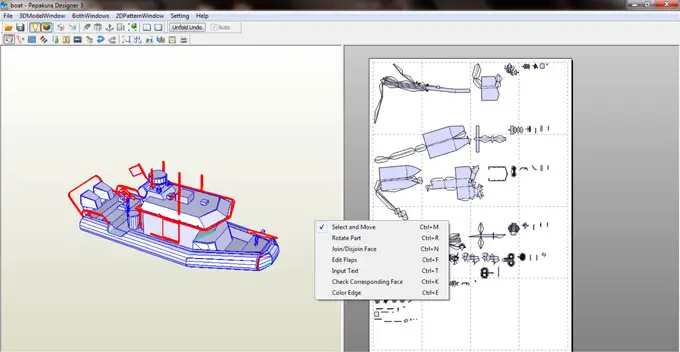
Now we are going to work with the boat. Open boat.obj in Pepakura and then unfold it by clicking on the Unfold button. In 2DPatternWindow again choose Change the Scale of Development - Specify the scale again and replace the scale with the scale which we already got earlier, replace it with 1.797677 then click ok. Now we have a messed up template with 1:50 scale, an 18 cm model of a 9 meters boat. The next tutorial will cover how to arrange and layout that messed up pattern / template, but you can found out yourself by using tools in the right column, by right clicking on it. If you want to know where we are now, we have reach a half way done, we still need to work on : 1. Setup the template in pepakura, 2. re-draw template in Inkscape, 3. Apply the re-drawn template in 3d again in Gmax, 4. Coloring the template in Inkscape and cross check it on Gmax, 5. Making instructions and finalize the template in PDF. Well it’s enough for now.
You must agree on Document License agreement page first, choose agree on the radio button then you will proceed
Download
Open the RAR file with WinRAR (recommended software)
Tutorial files so far download here :
3D Tutorial maker files (setting up blueprint)
3D Tutorial maker file 2 (modeling)
